NK17SGB is a key component for radiography systems. This page covers its key specifications, available models, typical applications and FAQs so you can confirm the right model and request a quote. Available models: NK17DG, NK14DY, NK14DG.
Available Models
Key Specifications
| Item | Specification |
|---|
| Suitable size of clip | 5 ” × 7″ – 14 ” × 14″; |
Applications
- Radiography / fluoroscopy systems
- (add other typical use cases from the datasheet)
FAQ
- Q: What models are available?
A: NK17DG, NK14DY, NK14DG
- Q: How do I choose the right one?
A: Match the specifications above to your tube, generator and workflow, then contact us for a recommendation.
Related Products
Contact
Need a quote or selection advice? newheekaide@gmail.com · +86 13356723728 · Contact form
NK17SGB: Specifications & Selection Guide
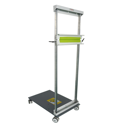
Bucky Stand is the auxiliary equipment of X-ray machine. By combining the medical X-ray machine and the device, the head, chest, abdomen, pelvic cavity and other parts of the human body can be examined by taking pictures to achieve the purpose of diagnosing lesions. The common name of this product is bucky stand and its trade name is the vertical photographic frame.
Bucky stand equipped with a mobile device, which can be flexibly moved to different positions according to the needs of medical institutions.
## Structure and technical parameters
1. Structure
The device is composed of three parts: box cover, slide rail and film clip.
2. Technical parameters
(1) The travel of the camera frame is not less than 1400mm;
(2) The maximum size of the cassette/IP board/Flat Panel detector: 17″ × 17″.
## Installation operation
1. Installation
(1) After placing the column flat, align the three screw holes of the base with the three Φ11 through hole centers at the bottom of the box body, and tighten them with three M10 screws.
(2) Move the device to make the vertical center of the film box coincide with the center of the bulb to maintain the best clarity of the film;
Use three expansion screws to fix it on the wall 50cm above the ground
## Use
Push the bucky stand to move the bucky stand to the required position;
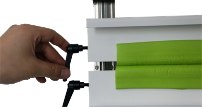
After adjusting the lower clip to the appropriate height, lock the handles on both sides, clamp the selected piece box (or IP board, flat panel detector) into the moving clip, push the clip upward, so that the piece box (or IP board, flat panel detector) is placed in the upper and lower clip, and clamp tightly;
After the shooting is completed, pull out the film car, and remove the film box (or IP board, flat panel detector) from the film clip; And push the film cart into the film box.
Note: When the chip box (or IP board, flat detector) is taken out, the moving clip should be slowly dropped back to prevent the force from being too strong, causing damage to the clip and slide.
## Precautions
1. When installing, try to keep the contact degree between the vertical center of the film box and the tube consistent, otherwise there will be a phenomenon of light and dark on one side;
2. Ensure that the convergence distance is about 180cm to maintain the clarity of the radiography;
3. Pay attention to the selection of radiography conditions (kV, mA).
4. Adjust the position of the device and lock the brake wheel to prevent the position change from affecting the radiography effect.
5. Do not stand on the base of the mobile device to prevent sliding and falling.
## Environmental conditions for transportation and storage
In the transport or storage packaging state, the equipment must be able to stand for more than 15 weeks under environmental conditions not exceeding the following range; in the transport or storage packaging state, the equipment must be able to stand for more than 15
Temperature -40°C——55°C
Humidity ≤90%
Atmospheric pressure 500kpa——1060kpa
Store in a non-corrosive gas and well-ventilated room.
## Repair and maintenance instructions
1. Repair
(1) The relevant provisions of equipment maintenance, maintenance personnel must comply with. Maintenance personnel without our authorization shall not repair the equipment without authorization;
(2) After equipment maintenance, all safety-related devices must be checked before use;
(3) Often check the rail and other transmission parts regularly, and add an appropriate amount of 30# oil or grease.
2. Maintenance
The product should be maintained during use to ensure that the product works normally and gives full play to its effectiveness.
(1) The machine room is often kept clean and dry, and the surface of the moving track is often wiped, without dust and debris;
(2) Regularly check whether the brake wheel is in good condition and the brake opening key is normal.
3. Advice
(1) The contact clearance adjustment between the moving parts and the track bearing assembly shall be carried out once a year;
(2) The product should be repaired by professionals after failure.
(Note: If there are design changes and specification changes of this product, users will not be notified, subject to physical)
1) The manufacturer shall not bear any consequences caused by the violation of the safety regulations and precautions in the manual.
2) The Manufacturer shall not be liable for any unauthorized mechanical or electrical modification or misuse of the product the consequences and the financial compensation required as a result.
3) The free warranty period of the equipment provided by the manufacturer (non-human factor damage) is one year, and the warranty period starts from the equipment inspection date of use signature. Outside the warranty period, within the life cycle, to provide paid maintenance and accessories support, the product life cycle from the production date of ten years. Please refer to the product nameplate label for production date.
